

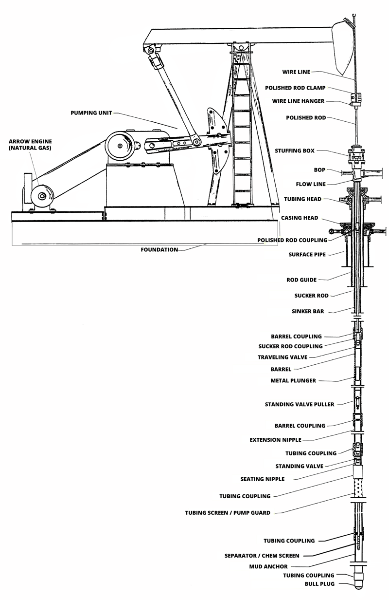
Arrow Engine (Natural Gas)

Wire Line
Wirelines are made up of either single strands or multiple strands of wire. They are either collecting data during well logging to assess formations, or transmitting data during workover operations. In simple terms, wirelines are essential for gathering information about wells and sending data when doing maintenance work.


